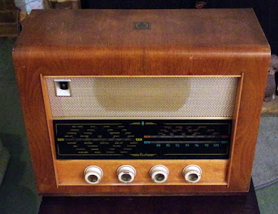
After being on my to-do list for the last 4 years, I've finally started work on my vintage family wireless.
This 1950s valve wireless was still working at the end of 2013, although the tuning mechanism had failed.
I bought 2 metres of cord from and eBay supplier, and set about getting it running.
about the Bush
Despite its name, the Bush VHF 54 was released in August 1955. Whatever possessed the Marketing people at Bush to call it the "54"? It appeared to be over a year old by the time it was released. But this radio did have a twin called the VHF 55.
The VHF 54 is an A.C. mains set originally costing £25 4s, while the VHF 55 is an A.C./D.C. version with an original price tag of £25 18s 5d. Using the Measuring Worth website, our VHF 54 would have cost the equivalent of between £600-£2,000 depending upon whether you use real, labour or income value as a comparison. My estimation is that it would have equated to 6-8 weeks wages for an ordinary working class man, at a time when most working people didn't have any cash 'left-over' at the end of the week, after paying the rent.
This radio has a VHF FM band, but unlike the other bands (MW & LW) which show station markers, the VHF band just has a frequency scale, and only covers part of today's band (in the 1950s the band was 88 - 94.6MHz). The BBC only started VHF transmissions on 2nd May 1955, so if you'd have bought one of these in August 1955 you would have been right at the cutting edge.
Oh, ...and you probably had to live within a 25 mile radius of the Wrotham transmitter in Kent, as this carried the only VHF service in Britain.
Oh, ...and you would have needed a Radio Receiving License, costing £1/year.
 |
| 19.75" x 15.25" x 8". What a beauty! |
But we didn't buy our set new. Dad probably gave someone a couple of quid for it during the late 1960s, by which time people would have been getting rid of this kind of wooden boxed wireless, in favour of some gawdy, shiny, plastic monstrosity.
Either way, this set has now been in our family for at least 50 years. It probably arrived right at the end of the Golden Era of Offshore Radio.
replacing the cord drive
The first step is to remove the chassis from the cabinet. I took the push-on control knobs off by simply pulling them straight off. Never try to lever them off, as this could break the plastic.
I also gave the plastic knobs a clean using an old toothbrush and plain water. There is no point in using a harsh cleaner, only to remove the lettering; its better to leave them a bit dirty than to spoil them.
Once the back has been removed, unplug the VHF aerial, MW/LW aerial and the octal chassis cable connector. There are 2 screws to remove that fix the chassis to the cabinet.
 |
| There are 2 screws to remove that fix the chassis to the cabinet. |
At this point, the 2 tuning pointers are still attached, so carefully slide the chassis forward no more than an inch. Rotate the tuning capacitor disc as necessary to gain access to the pointer & clips, then lift the clips upwards and out of the pointer slot.
These clips are shaped like a blunt arrow head, and fit pointing downwards into the pointer.
The dials/pointers run on a metal track which can be removed via 2 fixing screws.
This track was originally lubricated using a grease, but after a few years (probably within the first 25) this has turned into a thick wax-like substance. Initially I rubbed WD40 into the track in an attempt to remove the old grease/wax.
The pointers also have (what I assume to be) foam pads to maintain pressure against the track.
The pointers need to run freely on the rail, so once all components have been cleaned, I smeared the track with Vaselene Petroleum Jelly.
I bought 2m of 0.85mm thick cord from eBay, which seems to be a similar diameter and construction to the origin. The original cord is described as "glass nylon" and appears to have a stranded centre with a cotton-like outer covering.
This illustration was taken from the "Wireless & Electrical Trader" Service manual;
Once fitted, I moved the pointer clips to their approximate positions and then I ran the tuning control back and forward a few times to settle it in.
 |
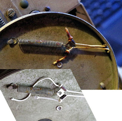
| top image is original, lower image is with new cord |
I've only fixed the cord with simple knots at each end at this stage. I want to leave it for a month or so before re-tensioning it to allow for temp/humidity changes which may cause the cord to 'stretch'. You can see that I need to increase the tension in order to expand the spring to match the original.
Before putting the chassis back in the box I did a quick repair job with Evo-Stik.
Getting the clips re-attached to the pointers is a bit tricky. I found it easier to use a kebab stick and the fingers of the other hand. That way I could still see what I was doing, rather than working 'blind'.
Another tricky operation is getting the points aligned to the scale.
 |
| use the vertical alignment marks at the end of each scale |
the acid test
After assembly and alignment, I powered the radio on and waited for the valves to warm up. All I could hear after several minutes was a faint crackling noise. I checked the anode voltage of each valve and found V3a was very high. I gave this valve a slight waggle with my finger; the set crackled loudly, I heard a voice, then it was gone.
V3 is an ECH81 triode-heptode (do what grandad? A triode has 3 terminals, a heptode has 7). The triode part is the local oscillator, while the heptode is the mixer (mixing the incoming signal with the local oscillator frequency produces an intermediate frequency of 470kHz, which is then amplified by the IF amp).
Clearly this valve was not making a good connection to the valve base, so I turned the power off and removed it. I really needed some Emery cloth/paper to remove some of the corrosion from the valve pins. The closest thing to hand was a Tom Pellereau Stylfile, which did the job nicely.
So now its working again on AM (MW & LW) which amazes me. I think I did some work on this radio in the early 1970s. I used to have access to a valve tester at Marconi, and can remember taking them all in and testing them. I replaced the 2 valves in the VHF rf section back then and got VHF working.
But I seem to remember VHF only worked for about 18 months. At the time I assumed the valves needed to be A1 for FM reception and left it at that. However AM continued to be used almost daily until about 2005 when a transistor radio took over duties.
It looks like I may have also replaced one or two of the capacitors. But I can't imagine that either the original designer, or the people on the line that assembled it back in the 1950s would have imagined that it might still be working 60 years later!
more to do
As already mentioned, sometime in the new year I will need to re-tension the drive cord. I also need to recheck the anode voltages for all valves, as this gives a reasonable indication of the state of the valves. It may also indicate whether any of the ancient capacitors are 'leaky' and need replacing.
The internal wiring is rubber coated, and although this looks pretty sound, I should probably re-wire with modern PTFE wire. I'm not looking forward to that job, so for the time being I don't leave the radio running unattended.
But I will replace the mains cable (which is actually plastic coated) with a new length of black 6 Amp 3 core. The fuse in the 13A plug is already 3A, but I've been monitoring the power consumption and it always seems to be below 40W (the service sheet rates it at 65W). So I may look for a 1A fuse to be extra safe.
I thought about buying a new set of valves (I've seen a set for about £45) but really, there is no need for the moment, its working just fine.


No comments:
Post a Comment