The next step in refurbishing my Bush VHF 54 wireless is to have a sniff around the valves.
I guess that anyone starting a career in electronics after about 1970 has never had to study (or work with) valves.
So here is a quick and simple primer.
Valves Vs Transistors
The first thing to appreciate is that valves and transistors are very different. While a cheap transistor radio is pretty harmless, there are at least 3 ways that an old valve wireless (like my VHF 54) could do you harm. It could; burn your house down, fall on your head, or (...and this is its favourite M.O.) zap you with 250V d.c.
As an apprentice in the late 1960s at Marconi, the old-timers used to say you should keep one hand in your pocket while working on a 'live' chassis. The idea was that if you got a shock, the current would not pass from arm to arm, through your heart!
The best advice is to think very carefully before you do anything when working on a valve wireless. Work in a tidy, well lit environment. Remove the power plug from the mains socket before handling or soldering components.
the thermionic diode
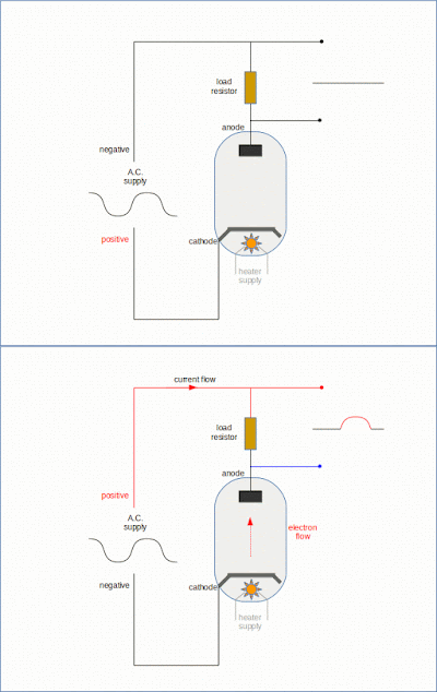
The diode just has two electrodes; an anode and a cathode. When the cathode is heated and the electrodes are correctly connected to a suitable d.c. supply, electrons will flow from the cathode to the anode.
 |
| This illustration shows the diode conducting in only one direction when connected to an a.c. supply. |
You only have to remember that electrons flow in the opposite direction to conventional current flow.
Here is an example of a full-wave rectifier using a double diode.
 |
| Full-wave rectifier circuit from Bush VHF 54 wireless |
A natural development of the thermionic diode was to add a controlling electrode.
the thermionic triode
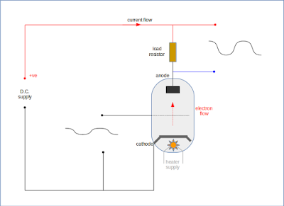
By adding a grid (or mesh) between the anode and cathode, the electron flow can be controlled.
 |
| a relatively small change in input voltage results in a large change in output voltage |
As the voltage on this grid (the control grid) becomes more negative than the cathode, the electron flow is reduced. As the control grid voltage becomes more positive, so electron flow from the cathode increases.
The invention of the thermionic triode was the start of the age of electronics, as it made it possible to design & build amplifiers and oscillators, paving the way for the introduction of "radio".
I have always believed that valves are easier to understand than bipolar transistors because they are voltage driven. The semiconductor equivalent to a valve is probably the JUGFET, where conduction (current flow) is largely determined by the voltage applied to the gate, rather than the base current, as is the case with a transistor.
Although there are linearity and stability issues associated with the simple triode, the basic "model" of how a triode works can be carried over when considering the more sophisticated valves like tetrodes, beam tetrodes & pentodes. The extra electrodes in such devices are simply attempting to control wayward electrons, reduce inter-electrode capacitance, and improve performance.
 |
| the Bush VHF 54 audio output stage |
The illustration above shows a typical audio output stage using an EL84 pentode. The additional electrodes are the 'screen grid' (connected to a high voltage) and the 'suppressor grid' (internally connected to the cathode). The cathode resistor (R30) creates a negative control grid potential relative to the cathode. It also introduces an amount of negative feedback.
Valve designers were/are good at integration; i.e. packing more than one valve type into a single glass envelope. For example, my wireless includes a triode-heptode (ECH81) and a triple diode-triode (EABC80).
Even if you don't possess a vintage valve wireless, a guitar amplifier or a modern valve hi-fi amp, there is a very good chance that there will be at least one valve in your house ...probably in your microwave oven.
I understand that valves are still the best option for high-power transmitters.
The age of the thermionic valve is not yet over!
measuring valve voltages
I'm lucky enough to have a couple of service data sheets for my Bush VHF 54; one was produced by Bush, the other by 'Wireless & Electrical Trader'. Each datasheet has additional information to the other, and both include reference voltages dotted around the circuit.
Both circuits specify that voltage readings were taken on an AVO meter. This was very important back in the 1950/60s because some meters have a greater affect on the measurement than others. My first multi-meter was a 1,000 ohms per Volt device. So even on the 10V d.c. range it was like slapping a 10k resistor across the circuit, and would often be useless on any but a low impedance circuit.
 |
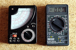
| Analogue or Digital? |
I've heard some people say they always use an AVO because a modern digital volt meter gives a higher reading (due to its higher impedance). But looking at the voltage test points on my Bush circuit I don't believe it will make any difference. They are all at relatively low/medium impedance points, such as across a cathode resistor, a supply point, a screen grid or an anode.
On my Bush wireless, the d.c. supply voltage is reading about 235V instead of 260V. This could be due to the rectifier (EZ80), the electrolytic smoothing capacitors, or a combination of both. So I've ordered replacement capacitors and a valve. Once the supply has been brought back to 260V (ish) I'll be in a better position to review the other valves.
I have also ordered a new 'magic-eye' (EM80) as I'm pretty sure that this has failed altogether. Thermionic valves do have a reasonably long life, and its often the problem of air leaking into the vacuum which degrades their performance.
At the moment I have no desire to get VHF/FM operation working, as I see the attraction in this wireless as an AM (MW & LW) receiver. In addition, I would have to remove the FM sub-assembly from the chassis in order to gain access to the two valve bases.
I have this type of radio and have a notion to restore it as a project despite knowing nothing at all about electronics. It has no magic eye in the little square window on the left hand side of the set, so I guess I need one of those too. I am sure your posts about this radio will be very helpful. Thank you.
ReplyDeleteClearly the high voltages inside an old valve radio like this one are dangerous. Also, its very likely that the internal wiring has perished, and thereby a potential fire risk. (see this post: http://captainbodgit.blogspot.com/2017/12/bush-vhf54-rewiring.html)
ReplyDeleteI strongly suggest you find someone with electronics experience to help you with this project.
Stay safe and good luck.