A few spare parts arrived this week, so I made some progress with refurbishing this wireless.
Its now a working set, although there is a lack of sensitivity on all wavebands.
However, I can tune in stations on all three wavebands and the tuning scale is now nicely illuminated.
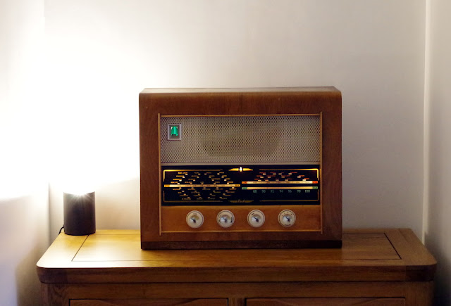
With three new dial bulbs fitted (6.5V 0.3A) and a new EM80 'magic eye' tuning indicator, our Bush wireless is looking more like its old self.
Although the magic eye glows a nice shade of green, it does not do what it is supposed to do, except on the strongest medium wave station (Talk Sport). The green line should widen as you tune into stations, but as the radio is not very sensitive, there is very little change in the AGC voltage which drives the magic eye.
VHF FM band
I didn't spend any real time investigating the problem with the VHF band, but I ordered a spray can of switch cleaner and used it on the waveband switch. I only had to operate the switch a few times before VHF came back to life.
The sound quality is pretty poor on VHF and the sound level is low. Audio distortion seems to vary as you tune through the signal, as if there may be a problem with the FM discriminator. If I tap the control knobs I also get a ringing sound, which I assume is due to a microphonic valve (maybe I need a new pair of EF80's for the VHF tuner & frequency changer).
HT supply
Replacing the double-diode EZ80 rectifier valve had an immediate effect on the HT supply. According to my circuit diagrams, the HT should be 260V d.c. (I have one diagram by Bush, the other is from 'Wireless & Electrical Trader'). Before replacing the rectifier, I was only getting 234V. This rose to 254V with the new valve fitted.
Although this still looks a little low, I currently have the mains transformer selector set to 250V. My mains monitor has been running for the last few hours with readings between 225-235V a.c. So I should probably reset the selector to 230V.
AM frequency changer
I also ordered a new ECH81 triode-heptode because this valve was intermittent in its valve base, and also because the test voltages were rather low. Unfortunately the new valve is still intermittent as the problem seems to be with the valve base, rather than the valve. Also, the anode voltage of the triode is still very low, so I guess there is a problem in the associated circuitry.
Intermediate Frequency (I.F.) amplifier
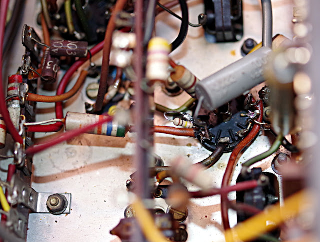
The IF amplifier valve is an EF85, and the screen grid voltage was higher than expected. This was largely due to a 100k resistor that had gone open-circuit. I replaced the large original 100k carbon resistor with a small, modern, carbon film equivalent which looks a little lost in the chassis.
 |
| The grey R.S. capacitor on the screen grid must have been fitted by me during the late 1960s/early 1970s |
I may have to replace many more resistors and capacitors, but it seems a shame to replace these old, large components with modern equivalents, which will change the appearance of this 1950s wireless chassis forever!
 |
| Access to the components under the chassis is via a removable wooden panel |
Having reassembled this wireless, I noticed that the Tone control knob does not push back flush to the cabinet. For some reason the shaft sticks out further than the other controls, so I will have to dismantle the wireless again and put it right.
Having re-tensioned the tuning cord drive, I'm very pleased to find that this now works perfectly with no hesitation or slipping.
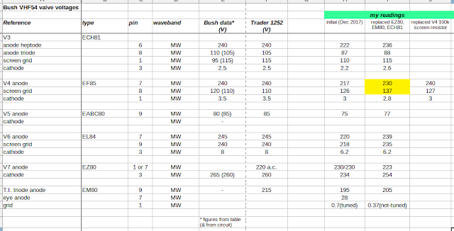
I have recorded certain test voltages against the values listed in both the Bush and Trader circuits. The bush service sheet includes voltages on the circuit and separately in a table. I don't understand why these two references are sometimes different.
valve test voltages
I have recorded certain test voltages against the values listed in both the Bush and Trader circuits. The bush service sheet includes voltages on the circuit and separately in a table. I don't understand why these two references are sometimes different.


No comments:
Post a Comment