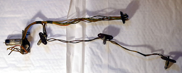
Some of the rubber coated wiring in our family wireless was so badly perished that it just snapped and dropped off the wire when moved.
There was a real danger that one of these bare wires would come into contact with one of its naked neighbours, possibly causing damage to the set.
Therefore I just had to remove and rewire the main wiring loom to make our wireless safe.
This may sound strange, but I swear that the black wires were the worse. They were so rigid that I could not bend them even slightly, as the insulation simply broke into a dozen bits, whereas some of the lighter colours were still quite flexible.
In some cases, it was difficult to determine the true original wire colour, as they were so badly faded and discoloured.
 |
| wiring running up from the chassis to the scale lamps, magic-eye, speaker & LS socket |
The first step was to look at the wiring and relate it to the circuit diagram. I recorded the connections in tabular form on a spreadsheet, and took a few photos.
I removed the old wiring loom from the cabinet, complete with lamps and the "Magic-eye" tuning indicator sub assembly. To do this I had to cut a few wires that terminate at the speaker and audio transformer.

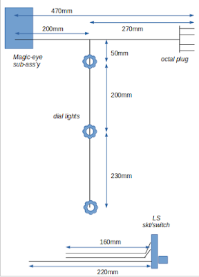
The next step was to note a few measurements and create a simple dimensioned loom drawing.
 |
Note that the dimensions are for the final wire lengths after twisting wires together. Light use of a hair-dryer will help the twisted wires hold their new shape.
I have used 16/0.2 PTFE covered wire, and haven't completely followed the original wire colours. In 2 cases I've used purple and pink as I didn't want to use brown & green twice.
The original wire looks thicker than the new stuff, but that is because the rubber insulation is quite thick. The original has 13 strands, so I guess its 13/0.2 or whatever the old imperial measure version was.
As the scale lamp holder body is quite exposed, I connected the chassis potential side of the 6.5Volt line to the body to minimise the risk of this being accidentally shorted to the metal work.
I also checked the resistance of the inter-anode resistor on the base of the EM80 Magic-eye. As this should have been 470k but was 665k, I replaced it with a modern 0.25W 470k resistor. However, this has not fixed the "magic-eye" function, so I probably still need to replace the valve.
 |
| new wiring loom fitted & the wireless still works! |
The vivid wire colours look a little out of place, but I guess they should fade ...in the next 50 years maybe!
As soon as I can get my hands on 2m of black 6Amp, 3 core cable, I will replace the existing 2 core mains cable and ensure a safety earth to chassis.
soldering on a grander scale
I only have an 18W Antex soldering iron with a pointed bit. This is great for use on circuit boards, but hard going on the larger scale components used in a valve radio. So I may have to invest in a more powerful one with a larger, flat-faced bit.
See also: https://captainbodgit.blogspot.co.uk/2017/12/bush-vhf54-replacing-drive-cord.html

No comments:
Post a Comment