I received another bag-of-bits type Christmas present in 2015.
This one contained nuts, bolts, bits of acrylic, wheels, motors and a battery holder.
Despite being involved with electronics for over 50 years, I have zero experience with robotics.
This kit is one of those brilliant robot car chassis kits from China. This one has two driven wheels and a passive castor at the back.
The acrylic chassis has cut-outs which I assume are for standard parts such as bumper switches.
 |
| Mug of tea not supplied |
The Buggy is larger than I'd expected: 160mm wide x 220mm long, with 70mm diameter wheels.
If I only had a brain
Once assembled, the buggy does absolutely nothing. That's because you need to give it a brain, interface it to the motors, and start programming. I decided to initially use a 14M2 Picaxe and buy an infrared range finder so it could see where it was going.
I couldn't see much point in using a Raspberry Pi for my first attempt. The Picaxe is easy to program via my Pi, it is not so picky about supply voltage, and it runs as soon as power is applied (unlike the Pi).
Construction follows classic Bodgit conventions, with the infrared sensor attached to the nose of the buggy using BluTack.
 |
| You have to supply your own BluTack |
I've built the electronics on a small breadboard, which adds another dimension to an already flakey project (if the buggy crashes into something, the Picaxe sometimes gets reset!). But the whole point of this project is to allow rapid development of software and hardware...
 |
| Picaxe/Pi programming link |
...and there are 3 female jumper leads hanging out the back so I can quickly connect to 3 male jumper leads and download a new program from my Pi.
Programming the Picaxe from a Raspberry Pi was covered in an earlier post, but there is a small modification to the Pi2Pic interface so that I can simply connect/disconnect without moving wires or using links.
 |
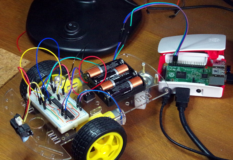
| All components are fitted to the Buggy, except the Raspberry Pi |
I've added an extra 10k resistor from 5Volts to pin 6 of the uln2003. When the Pi is disconnected, this resistor takes the driver input high, so the "serial in" pin on the Picaxe is pulled low, stopping the Picaxe from entering the program mode.
Initially I used an 18k resistor (only because it was the first one out of my resistor box) but I had some interference problems when the motors were switched from forwards to reverse. Lowering the resistor value to 10k fixed this problem.
Getting the wheels turning
When you apply power from the 4 AA sized batteries to the motors, the wheels turn one way. To be able to control the direction we need an H drive circuit. For this task I've chosen the L293D quad half-H drive chip. I've Gimped an illustration from the data sheet to show the configuration I'm using.
 |
| Two half H's give us an H |
Each motor forms the crossbar of an H, and the drivers are the up-rights. So if driver 1 is turned on and driver 2 is turned off, the motor rotates in the opposite direction as it would if driver 1 was off and driver 2 was on.
So for each motor I need 3 control outputs from the Picaxe: forward, reverse and go. Forward and reverse must always be the opposite of each other (i.e. if you set forward "high" you must set reverse "low").
Since my buggy supply is just 4 x AA batteries, Vcc1 and Vcc2 are linked together.
I am using the D version of the L293 which includes protection diodes which dissipate the "back emf" generated when you remove the power from any kind of coil (inductor). It's just not worth getting a regular L293 and fitting the diodes yourself.
It is normally a good idea to add capacitors directly across the motor terminals to suppress noise. Unfortunately the only small 0.1uF capacitors I have at the moment have short wires, so I can't use them. However, I don't seem to be getting any noise problems.
Let there be light
My chosen "range" sensor is a Sharp GP2Y0A41SK0F which produces an analogue output voltage, inversely related (roughly) to detection distance (i.e. the voltage generally increases as the sensor gets closer to an object).
The output reaches a peak at about 3Volts for a detection distance of approximately 30mm. Any closer, and the voltage starts to drop back to zero. So it may be an idea to mount the detector inboard by 20-30mm, so it never gets stuck driving the wheels forward when it comes eyeball to eyeball with a wall. (But I haven't done this).
My first program
I decided NOT to go looking at other peoples programs (where is the fun in that?) so I used the simple strategy of "turn right when you detect something" in my first program. This approach had an obvious flaw, in that the buggy would get stuck in tight corners.
So the mk 2 program includes a "reverse if you get stuck" feature. While the buggy normally turns right when it sees a object some distance away, if the sensor voltage is higher than a certain level, the buggy now reverses.
I've also added a 200ms pause when the buggy turns. This was because the buggy tended to only turn away until it no longer saw the obstruction. This sometimes led to the buggy hitting the object at a slight angle (basically the buggy has tunnel vision). This short delay forces the buggy to turn more than it needs and (usually) avoid the object.
'**********************************************************************************************
'RoboBuggy
'--------------------------
'This Picaxe 14M2 program controls a two wheel buggy.
'The ADC monitors range finder voltage
'SteveDee
'Jan 2016
'***********************************************************************************************
'word w0: byte b0 is used as a loopcounter
'word w1: used for ADC reading
'Picaxe pin 2: Program Picaxe
output B.2 'LED
output B.3 'motor#2 enable
output B.4 'motor#2 forward
output B.5 'motor#2 reverse
output C.0 'motor#1 enable
output C.1 'motor#1 forward
output C.2 'motor#1 reverse
symbol EYE_BALL = C.4 'ADC input: obstruction detector
symbol LED = B.2
symbol M1_EN = C.0 'motor#1 enable
symbol M2_EN = B.3
symbol M1_FWD = C.2 'motor#1 forward drive
symbol M1_REV = C.1 'motor#1 reverse drive
symbol M2_FWD = B.5
symbol M2_REV = B.4
for b0 = 0 to 10 'wait 6s after power switched on
high LED 'flash that LED...'cos it looks nice!
pause 300
low LED
pause 300
next b0
main:
readadc10 EYE_BALL,w1 'check for obstructions
if w1 < 80 then 'pretty clear ahead, so go forwards
low LED
low M1_REV 'straight ahead
high M1_FWD
low M2_REV
high M2_FWD
high M1_EN 'Go!
high M2_EN
else
if w1 <250 then 'Robo is approaching an object, so turn away
high LED
low M1_EN 'stop M1
high M2_EN
pause 200 'turn more than may be necessary
else 'Robo must be very close to an obstruction...
high LED
low M1_EN '...so stop & then reverse
low M2_EN
pause 700
high M1_REV 'reverse M1
low M1_FWD
high M2_REV 'reverse M2
low M2_FWD
high M1_EN
high M2_EN
pause 700
low M1_EN
low M2_EN
endif
endif
goto main
You can chock the buggy up with the wheels off your bench/desk and do provisional testing with the Pi still connected. This is very useful to test that the sensor is detecting objects and that the program is taking the required action.
An unexpected benefit of my design is the inclusion of an LED. This flashes ten times when the program starts, and turns on when the buggy sees an object in its path. I had a problem at one stage where the Picaxe would reset due to interference. I don't think I would have recognised it was doing this if it had not been for the flashing LED.
Things to do
It is a bit tedious having to set M1_REV low wherever I set M1_FWD high (and visa-versa). All I need to do is wire an invertor into circuit so that when one input is high, the other is low. I have spare drivers in my ULN2003, I just need to do it!
Eyes in the back of my head: adding an extra infrared sensor to the back of the buggy would stop in reversing into things.
Adding sound might stop people tripping over it.
Develop a strategy/algorithm whereby RoboBuggy actually explores an area, rather than simply moving around in a semi-random fashion.
Add a transmitter, so I can send telemetry back to the pits! (...maybe getting too carried away with that one).
Conclusion
I think one of the reasons that I have never played with robots until now is that I thought; "OK, so you build a robot, play with it for a couple of hours, then never touch it again!".
I now think there is a bit more to it. I think its addictive. You load a program, watch the robot stumble around the room for a while and think "I'm sure I can improve on that strategy".
No comments:
Post a Comment